
How Sirius Worked
A three-controller design, a dedicated display processor, and an operating system developed in Lahore.
Architectural Overview
Sirius grew from work begun in Lahore around 1999–2000 into a self-contained handheld with three cooperating 8-bit controllers. The recovered hardware and firmware show how applications, graphics, and keyboard handling were divided across inexpensive parts.
Rather than overburdening a single CPU with display refreshes, keypad matrix debouncing, real-time clock monitoring, flash filesystem parsing, and application logic, Sirius divided responsibility across three Atmel AT89C51RD2 microcontrollers clocked at 40 MHz communicating over dedicated parallel and interrupt lines.
The Tri-Microcontroller Pipeline
Each of the three controllers executed a discrete, purpose-built firmware image compiled with Keil C51 and clocked at 40 MHz in the recovered configuration:
1. Main Application Controller (CPU)
Running process_controller.hex, the Main CPU managed the execution of AlephOS 2.0. Its responsibilities included:
- Kernel & Scheduler: Cooperative multitasking loop managing application states, event routing, and system power transitions.
- Virtual Machine (AVM): A bytecode interpreter allowing dynamic applications to execute from MMC storage without reflashing firmware.
- FAT16 Filesystem: Reading and writing standard FAT16 partition tables on external MultiMediaCards. Constrained to single-sector clusters for high-speed deterministic block access.
- Math Engine: Reverse Polish Notation (RPN) scientific calculator implementation with trigonometric and logarithmic functions.
- Communications: RS-232 serial link handshaking for PC synchronization and backup.
2. Display & Graphics Coprocessor (GPU)
Running Glcd_rb2.hex, this processor acted as an intelligent graphics controller, insulating the Main CPU from display timings:
- Dual KS0108 Driver: Generating parallel control strobes (CS1, CS2, E, R/W, D/I) and driving data bytes across the 64-column centerline.
- Command Parsing: Decoding rasterization commands streamed from the Main CPU over an 8-bit inter-processor bus.
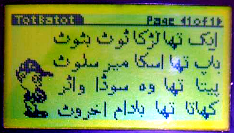
- Glyph Rasterization: Blitting 3×5 micro fonts, 5×7 system fonts, 10×16 numerals, and proportional Urdu Arabic-script bitmaps from ROM tables.
- Dirty-Region Blitting: Buffering window frames and redrawing only updated client rectangles to prevent STN liquid crystal ghosting.
- Hardware Flow Control: Asserting a busy line back to the Main CPU during panel access to prevent buffer overruns.
3. Keypad & Matrix Controller (KBD)
Running keypad_rb2.hex, this processor was dedicated to input scanning and acoustic feedback:
- 8×8 Matrix Scanning: Continuously driving 8 row lines and sampling 8 column lines across 56 physical alphanumeric keys.
- Dedicated Softkeys: Scanning six top-row contextual function keys (F1–F6) aligned directly beneath the screen’s on-screen button labels.
- Hardware Debounce: Multi-sample filtering and 2-key rollover rejection to eliminate bounce noise on tactile membrane switches.
- Modifier State Machine: Maintaining hardware latches for Shift, Function, and Alpha states with dedicated discrete status lines.
- Acoustic Transducer: Generating frequency-synthesized square waves to drive the onboard piezoelectric buzzer for keyclicks and alerts.
- Bus Assertion: Latching keycodes onto the shared data bus and pulsing the Main CPU’s external interrupt line (INT1).
The Operating System: AlephOS 2.0
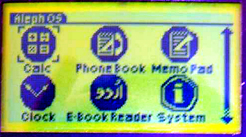
AlephOS was written completely from the ground up in C. Unlike embedded monitors that executed monolithic programs, AlephOS provided a unified GUI environment with consistent window frames, dialog boxes, scrollable list views, file pickers, and softkey button bindings.
Surviving applications recovered from the project archive include:
- Launcher: File and application navigator parsing MMC directories.
- Phonebook & Order Form: Commercial field-data collection tools.
- Urdu & English Readers: Dual-language ebook readers with pagination.
- RPN Scientific Calculator: Stack-based evaluation.
- Graphics Demos: 3D wireframe bounce, Conway’s Game of Life, Snake, and dithered image viewers.
Inter-Processor Bus & Handshaking Protocol
Communication between the three 8051 controllers relied on a tightly synchronized bus architecture designed to prevent bus collisions and instruction overruns:
- 01 · Command PhaseMain CPU places command on Port 0, selects GPU via P1.0–2 demux, and pulses P3.5 low (triggering GPU INT0).
- 02 · Parameter StreamGPU reads Port 1 and receives argument pairs. GPU asserts P3.4 high (“Busy”).
- 03 · Panel ExecutionGPU blits pixels to KS0108. Main CPU spins on P3.2 waiting for Busy to clear.
- 04 · Key InterruptKeypad MCU detects keypress, asserts keycode on P1, and trips Main CPU INT1 (P3.3).
Because the keypad controller drove the Main CPU’s Port 0 while signaling an interrupt, the Main CPU’s interrupt handler (Keyinterr) floated Port 0 to 0xFF, latched the incoming scan code, and held the request line until the vector completed, eliminating race conditions between keyboard input and graphics streaming.
Hardware Specifications
Physical and electrical specifications reconstructed from surviving schematics, Gerber PCB files, and firmware manifests:
| Subsystem | Specification | Engineering Notes |
|---|---|---|
| Main CPU | Atmel AT89C51RD2 @ 40 MHz | 40 MHz clock; 64 KB Flash, 1,792 B RAM |
| Graphics Coprocessor | Atmel AT89C51RD2 @ 40 MHz | Dedicated GPU; executes Glcd_rb2.hex; drives KS0108 panel timing & glyph blitting |
| Keypad / I/O Controller | Atmel AT89C51RD2 @ 40 MHz | Scans 8×8 matrix; hardware debounce; PWM frequency synthesizer for piezo audio |
| Display Panel | 128×64 Monochrome STN LCD | Dual Samsung KS0108B drivers (CS1 Left 64×64 / CS2 Right 64×64); LED backlight |
| Video Memory | 1,024 Bytes (8,192 Pixels) | Organized as 8 vertical pages × 128 columns; 1 bit per pixel |
| Removable Storage | MultiMediaCard (MMC) / SD Slot | SPI mode interface; FAT16 filesystem; formatted to strictly 1 sector per cluster |
| Real-Time Clock | Dallas DS1302 Trickle RTC | 3-wire serial interface; 32.768 kHz quartz crystal; battery-backed timekeeping |
| Serial Communications | RS-232 via MAX3232 | Full-duplex serial UART up to 115,200 baud for PC synchronization |
| Keyboard Matrix | 56 Keys + 6 Softkeys (F1–F6) | Tactile dome matrix; dynamic softkeys contextually bound to on-screen UI buttons |
| Audio Output | Piezoelectric Acoustic Transducer | Driven via hardware timer PWM; produces tactile key clicks and musical alert tones |
| Power Subsystem | 3.7V Rechargeable Cell | Low-dropout (LDO) linear regulators supplying dual 3.3V and 5.0V voltage rails |
| Operating System | AlephOS 2.0 | Written in C, compiled with Keil C51; includes AVM bytecode virtual machine |
| Museum Accession | CHM Catalog #102718536 | Inducted into Computer History Museum permanent collection in 2013; Donor: Amir Husain |
Preservation & Emulation Notes
The modern emulator is implemented in Rust (crates/i8051-test-runner and aleph.exe). The emulator runs all three 8051 CPU cores in deterministic lockstep, accurately simulating bus timing, demux gating, the KS0108 panel’s two-cycle read latency, and SPI MMC communications.
During archival analysis of the recovered firmware binaries, one historical defect was identified in the display ROM (Glcd_rb2.hex): in the routine servicing window background drawing (command 0x0C), an instruction was found calling the system screen bitmap rather than the clean window background frame, causing application text to be blitted over the system info graphic. The emulation preserves both the original binary and a version with the display defect corrected for legibility (patching two bytes at offset 0x2775 to restore the commented-out window call).
← Return to the Sirius Object Study · Launch the Interactive AlephOS 2.0 Emulator →
The cost of every design choice
The three controllers, switch keyboard, small LCD, and hand-solderable construction grew from Sirius’s $50 goal. Follow the object story and estimated parts ledger to see how manufacturing in small quantities shaped the architecture.